THE FLUID CONSERVATION OF MASS EQUATION
The conservation of mass is one of three basic fluid fundamental laws (or general physical laws actually). This principle actually is quite simple to understand, a person doesn’t need to become a fluid engineer to calculate the mixture total weight of 100 grams of coffee mixed with 200 grams of milk, it simply becomes 300 grams of coffee milk.
This law not only governs the fluid flow problems, but it also can be applied to a chemical formula such as the mass balance of oxygen and hydrogen reacted to become water. 32 kg of oxygen reacts with 4 kg of hydrogen will form 36 kg of water.
This law is very universal in nature, we can apply this mass conservation law for every engineering problem in the earth as well as anywhere in the universe. The only exception for this law is Einstein’s mass and energy equation E = m.c2, which states that mass can be converted into energy when the mass is “disappear”, but this condition rarely happen in fluid dynamic problems, and only relevant for most nuclear reactions and near the speed of light physics problems. So, we can ignore this relation in our following discussion.
In fluid mechanics problems, sometimes it is not useful to determine the amount of mass of the fluid, imagine if you should measure the total mass inside a long pipe, or maybe the total of air comes out from an air conditioner system: it will become a tedious activity and not feasible with our measurement devices. To better formulate this mass conservation law, in fluid mechanics, we often used the rate of change of the mass or known as mass flow rate, defined as the amount of mass divided by the time.
mass flow rate = total mass / total time
In this form, the conservation of mass law sometimes called the continuity principle. For example, one could easily measure the mass flow rate of flow through a pipe in kg/s or maybe kg/hour with a flow measurement device without having to know the total amount of mass along the pipe.
From this mass flow rate idea, the fluid conservation of mass can be defined as total mass flow rate comes in a control volume will be equal to mass flow rate comes out a control volume plus the mass increasing/decreasing rate inside the control volume, or mathematically:
mass flow rate in = mass flow rate out + rate of mass change in the system
Imagine if we have a bath up with water tap opens and flow with mass flow rate 1 kg/s, then we open the bottom drain causes the flow out about 0,8 kg/s, we will find our bath up will fill with water in 0,2 kg/s rate. Quite simple right?
In an internal flow such as pipes or tubes, the mass flow rate can be calculated using the following equation:
mass flow rate = density*area*velocity
Another important concept of mass conservation law is the volume flow rate or simply flow rate. This is a very useful concept if we want to analyze an incompressible flow such as water, oil, or air at low-speed operation. (Incompressible flow is a flow with negligible density change with respect to pressure, temperature, time, etc.). The volume flow rate mathematically described as:
Volume flow rate = area*velocity
If we consider a steady-state flow (rate of mass change inside control volume = 0), we can rearrange the conservation of mass equation in the form of volume flow rate as:
area 1 * velocity 1 = area 2 * velocity 2
The above equation is a very important relationship between area and velocity in incompressible flow, it simply states that if we decrease the area, we will increase the velocity or vice versa.

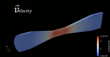
From the above picture, we can see the flow of fluid inside a ventury device. The flow inlet is on the left and flows in the right direction. We can see low-speed flow at the inlet (colored blue) then become faster (colored red) at the center of the ventury as the cross-sectional area decreases. Then, the flow velocity gradually becomes slower as the cross-sectional area grows streamwise.
The same principle we often use in our daily life is reducing the water hose outlet with our thumb to increase the velocity (hence increase the range of water) is actually the application of continuity principle.
Another example of this area to velocity relationship is the principle of airfoil’s aerodynamic shows below:
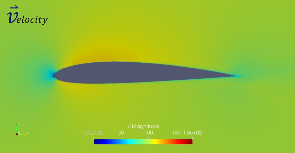
It can be seen that airflow velocity above the airfoil faster than under the airfoil. for the kinematics point of view, the curve-shape of the top airfoil surface creates a longer path for flow to reach the airfoil end, hence with the same given time will need a higher velocity.

Then, if we want to explain the above phenomena using a continuity point of view, we can make an imaginary line above the airfoil, then compare the “cross-sectional area” of the flow. We can see at the beginning (point 1), the velocity is similar to free stream velocity, then at the top part of the airfoil (point 2) cross-sectional area reduces, hence increase the velocity on the top of the curve, finally at point 3, velocity goes back to free stream velocity as the “cross-sectional” area back to its original size.
To read other articles, click here.
aeroengineering.co.id is an online platform that provides engineering consulting with various solutions, from CAD drafting, animation, CFD, or FEA simulation which is the primary brand of CV. Markom.

Leave a Reply
Want to join the discussion?Feel free to contribute!