VALIDATION AND VERIFICATION IN COMPUTATIONAL FLUID DYNAMICS (CFD)
One method commonly used in design and research in fluid mechanics and heat transfer besides analytical and experimental is using a numerical method known as Computational Fluid Dynamics (CFD).
This method has been used for a long time to solve any engineering problems (fluid mechanics related) in many industries, from aerospace, maritime, automotive, manufacture, energy and renewable energy up to biomedical engineering.
Because this method is computer-based (no physical prototype needed), the total processes can be done quickly, flexible, low cost, deeper and more importantly no safety issues if the test is related to human interaction.
Nevertheless, some engineers and scientists are still skeptical about the accuracy of the CFD result because of the lack of operational CFD knowledge. (no matter how sophisticated your calculator is, if you hit the wrong input the output will be wrong right?). In this article, we will discuss the verification and validation of CFD method.
First, before we discuss verification and validation, we must understand some terminologies, these are (1) code, (2) simulation, and (3) Model:
(1) CODE: Is a bunch of computer instructions to gives input and definitions. This code has a strong relation to what software we used. Different software will have difference code characteristics.
(2) SIMULATION: Is the use of the model, in CFD case this is to obtain the results such as flow, pressure, velocity, etc. based on the input to the model.
(3) MODEL: Model is a representation of the physical system (in CFD case is the fluid flow or heat transfer) to predict the characteristics or output of the system. For example the geometrical size, inlet velocity, temperature in the wall, pressure at the outlet, etc. based on the physical system we want to mimic.
Credibility of a code, model and CFD simulation are obtained based on its uncertainty and error level. The value of uncertainty and error itself determines whether the program and computational method used are fitted with at least intuitively and mathematically or not. Then, validation determines whether the simulation is fitted with physical phenomena or not. Generally, validation used experimental methods if possible.
There are some disagreements among professionals about the standard procedure of verification and validation of CFD simulation. Although CFD is widely used, this method is relatively new. CFD is a complex method that involves non-linear differential equations to solve the theoretical equations or experimental equations in a discrete domain, in complex geometry. Hence, the error assessment for CFD is based on these tree root (1) theory, (2) Experiment, and (3) Computation.
USING THE CFD RESULTS
The accuracy level of CFD analysis depends on the use of the result itself. The conceptual design process doesn’t need an accurate simulation result, on the other hand, on the detail design process, we need accurate CFD results. Every quantity in CFD needs a different accuracy level, for example, we don’t need accurate temperature value in the design process of low-speed aircraft, but we need accurate temperature calculation when we are dealing with supersonic aircraft or rocket. In general, there are three categories of CFD simulation based on its accuracy demand: (1) Simulation for qualitative information, (2) Simulation to obtain incremental value, and (3) simulation to obtain the absolute value of a quantity.
(1) Simulation to obtain qualitative information
In this case, generally, experimental information data are hard or maybe too costly to obtain, so there’s no comparison data, and what engineers or scientists need is the “how it works” information, and how to optimize a flow without needing the exact value of each parameter. For example, a valve manufacturer wants to develop a novel design idea, and they want to prove the theory and see whether or not the flow is streamlined or chaotic in nature, they don’t need exact value of pressure drop, velocity, etc. in this conceptual design step: At least until they want to compare this design to an existing design (refer to category 2) and want to design the minimum thickness of this part before it is ready to manufacture (refer to category 3)

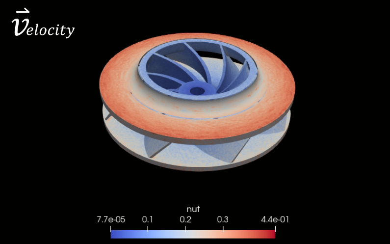
(2) Simulation to obtain incremental value
This scenario compares the incremental value with respect to some design or flows alteration with the same basic characteristics. For example, a company wants to modify an existing impeller blade in case of its blades number or its inlet angle (illustrates in the picture below). From this simulation, we could determine which impeller has the highest pressure difference regardless of its absolute pressure in the entire system. This type of simulation demands more accuracy than category 1.

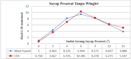
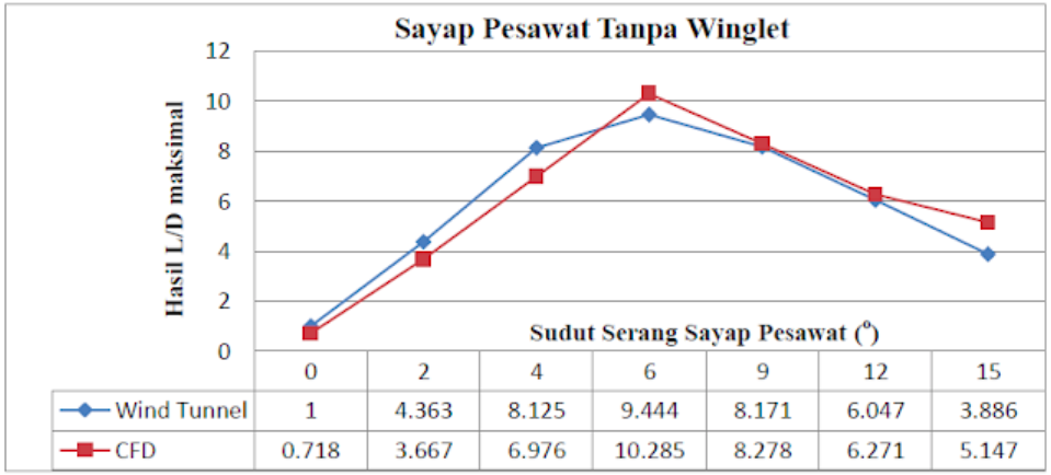
(3) Simulation to obtain absolute quantity
This is the most accuracy-demanding simulation scenario and sometimes this simulation results are compared with the experimental result to validate the method, and the other results are used in the next design process such as calculating the L/D of an aircraft wing illustrates bellow:
FLOW CHARACTERISTICS
To conduct a model validation, we must understand the flow characteristic to get intuition whether the flow acts as expected physical phenomena or not. For example, if we simulate a projectile with the speed exceed the speed of sound, the shock wave phenomena should occur; or if we simulate flow in pipe in low Reynold number, the flow should be laminar, otherwise, it must be turbulent, and so on. This knowledge is important because CFD is only a “calculator” if we hit the wrong input, the output will be wrong, in fact, the settings in CFD software, in general, are varied and cause a headache if we don’t have this knowledge.
PHYSICAL MODEL
Physical model not only refers to the geometrical model, but these are also the following models to be considered in CFD simulation:
(1) Spacial dimension
Or the geometry (1D, 2D or 3D) of the object we want to model, sometimes this model is simplified with symmetry or reduces 3D into 2D to reduce the computational effort as long as it still represents the essence of the flow we want to analyze.
(2) Temporal dimension
This is a time dimension of the simulation we want to conduct. This is very important in transient simulation, but not significant if we want to simulate a steady simulation. For example, if we want to simulates an object that rotates 1 rotation/second, and we input the delta time 0,1 second, we will accommodate the 10 incremental motions in our simulation. But, if we input delta time 2 second, the computation will error because we can’t accommodate the “motion” of the object.
(3) Navier-Stokes Equation
This is the fundamental equation of fluid mechanics that models the flow velocity, pressure, gravity, viscosity and even rotational force in the flow.
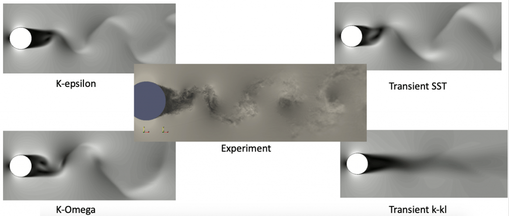
(4) Turbulent Model
This model is specially designed to model turbulent flow without calculating the whole (complex and computationally high effort) Navier-Stokes equation. The difference turbulent model we use will generate different results in our CFD simulation.
(5) Energy equation
Unlike classical solid mechanics, in fluid dynamics, energy generally refers to heat transfer and temperature change.
(6) Flow boundary condition
This is a mandatory input in our simulation. Boundary conditions input what flow characteristic we already have, for example, pressure in the inlet of a pipe (from a pump) or the velocity an aircraft during flight, etc.
CLOSURE
Even the setting in CFD simulation looks messy for CFD beginner, but a lot of scientists and engineers around the globe are publishing papers and journal continuously to share their setups and its accuracy compared to experimental as well as analytical results, hence CFD verification and validation becomes easier with these abundance references.
To read other articles, click here.
aeroengineering.co.id is an online platform that provides engineering consulting with various solutions, from CAD drafting, animation, CFD, or FEA simulation which is the primary brand of CV. Markom.


Leave a Reply
Want to join the discussion?Feel free to contribute!