THE BERNOULLI EQUATION
Using existing laws of nature, people could utilize those principles to develop engineering systems that changed the world. In fluid mechanics, one of the equations that really phenomenal because of its simplicity and tremendous usage is the Bernoulli equation.
There are three universal laws of the universe, (1) mass conservation, (2) momentum conservation, and (3) energy conservation. In solid mechanics, the momentum equation is described using Newton’s second law, F = m.a, similarly, in fluid mechanics, this law is described using Bernoulli equation (In fact, the most general and comprehensive mathematical expressions of momentum conservation is Navier-Stokes equation, but, it is very complicated mathematically).
To understand this principle, let’s make the mathematical formalization using this free body diagram:

Using well known mechanical energy conversion equation, the total of kinetic energy and potential energy will always be the same everywhere. Mathematically describes as follow:

With m = mass, g = gravitational acceleration, v = velocity, and H = height. In fluid mechanics, “energy” can be added by utilizing a pump to add pressure or sucks pipe outlet, hence the “pressure energy” term, E = p.V should be added on both sides of the equation.

with p = pressure, and V = volume. Then, we should realize that it is a tedious task or even impossible to calculate the whole mass and volume inside the pipe, what should we do is divide both sides with Volume so we can get:

with rho = is the fluid density. This equation is basically the well known Bernoulli equation. This equation is quite useful because it could predict the relationship between velocity and pressure. The following equation is for incompressible flow (constant density such as water), and negligible heigh difference. you can see how simple is this equation:

VENTURI TUBE AND EJECTOR
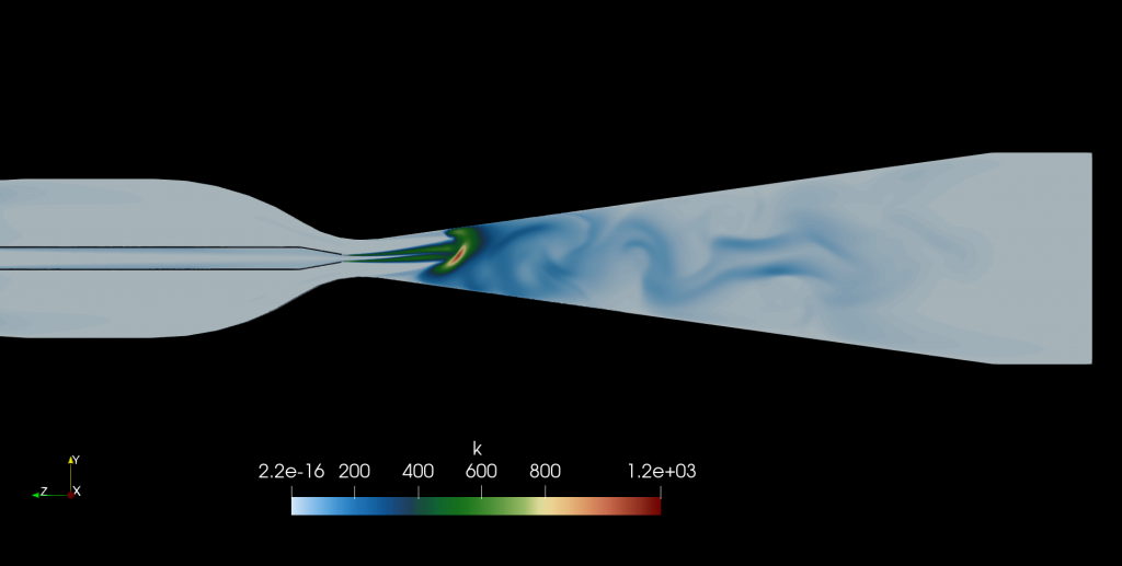
The above relationship is quite interesting, it is an inverse relationship between pressure and the square of velocity, it means if we have more velocity, the pressure will drop. Let’s discuss a venturi tube:

From the continuity equation (read here), we know that if we reduce the flow cross-sectional area, the velocity will be greater (as can be seen red-colored zone at the center), hence the pressure will be drop as the velocity increase quadratically. This pressure reduction can be calculated to measure the flow velocity, this is how venturi meter basically works.
The machine that has an identical principle as a venturi tube is the ejector. This device ejecting high-speed fluid through a nozzle and creates local negative pressure, this negative pressure sucks fluid from the neutral pressure chamber then push it to create flow. This is commonly used in industrial process applications:
AIRFOIL PRINCIPLE
Another example of this lift generation in an Airfoil as follows:

Imagine two particles flow from the leading edge (front of airfoil), one follows the top (curved) path and another follows the bottom (less curved) path, those particles will meet in the trailing edge at the same time, the curved path has longer traveling distance hence the velocity should be higher (This explanation is not proper for advance aerodynamics discussion, but good enough to understand this basic principle). Because of the higher velocity (colored red) at the top surface, the pressure expected to drop, hence creating suction to pull the airfoil upward (lift force).
This velocity and pressure relationship often causes a misunderstanding. If the flow velocity increase causes the pressure reduction, why if we shoot away higher-velocity water to our body the “pressure” we feel is greater? This statement is not totally wrong, but we must look closer in the flow region really close to our body, when the flow hits our body, the velocity in that local area suddenly became near zero in the normal direction to our body and deflected to the side, and as you can expect, the pressure has become higher significantly. This near-zero velocity region when the flow is hitting is called stagnation point.
TORICELLI THEOREM
The other interesting case of Bernoulli equation is the Toricelli theorem, see the free body diagram below:

The top tank and bottom tank are exposed to atmospheric pressure, hence P1 = P1. Then, the diameter of the top tank much larger than the bottom hole, so we can assume that V1>>V2, or V2 ~ 0. Then, consider H = H1-H2, we can rearrange the Bernoulli equation become:

This is a very simple and elegant equation to predict the flow velocity in the bottom of a tank with a hole versus its fluid height.
LIMITATIONS
And much more we can explore with the Bernoulli equation. Despite its usefulness, this equation, of course, has some limitations as follow:
- The flow is steady, there is no change in flow with respect to time.
- Inviscid flow, there is no viscosity (the tendency of the fluid to “sticking” to each other or to the solid wall) taking into account in this equation. The modeling of viscosity is accommodated in the Navier-Stokes equation.
- There is no shaft or fan power inside the flow.
- Incompressible flow, flow with thermal expansion effect can be analyzed using more comprehensive closure such as ideal gas equation or enthalpy equation in thermodynamics.
- There’s no heat and mass transfer
- The flow is along a streamline, no disruption of flow, no branches or turbulent flow.
To read other articles, click here.
aeroengineering.co.id is an online platform that provides engineering consulting with various solutions, from CAD drafting, animation, CFD, or FEA simulation which is the primary brand of CV. Markom.

Selamat PaGi nama saya Maharani saya kelas 2 Sd dan saya suka sekali dengan pesawat